
What can you do with a WIFI-IR Blaster?
A huge variety of devices use Infrared (IR) remote control; almost every TV, ROKU’s, electric fireplaces, projector screens, portable air-conditioners, etc. This is because IR has been around for a while and is cheap to implement. Wouldn’t it be cool to have a device on your network that can control any device in IR range? Luckily these WIFI-IR “blasters” are readily available, and cheap.
Now here’s the cool part, most of devices like these use a common WIFI-capable processor, namely ESP8266. And there is an open-source project (Tasmota) that is essentially a custom firmware for ESP8266-based devices allowing you to have complete control of the device. This allows:
- Breaking free from the firmware/software/apps that are bundled with the device
- Adding functionality not originally intended to be used
- Keeping the device on your local network – no worries about any “phoning home” to remote servers or shady mobile apps
- Using the powerful MQTT IOT protocol to communicate/control the device
This is a multi-part tutorial on how to:
- Flash Tasmota firmware to the WIFI-IR blaster
- Control and program the WIFI-IR blaster
(This post contains Amazon links, CircuitSnoop may earn a small commission for my endorsement, recommendation, testimonial, and/or link to any products from this website)
Getting Started
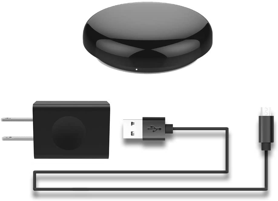
So, let’s get started. First, you can pick up one of these WIFI-IR blasters for under $20 readily. The brand listed below is not the exact same as the one used in the tutorial (as they are no longer available), but there’s a 99% chance that they use the same PCB layout or ESP8266 architecture.
Hardware Preparation: Flashing Tasmota Firmware
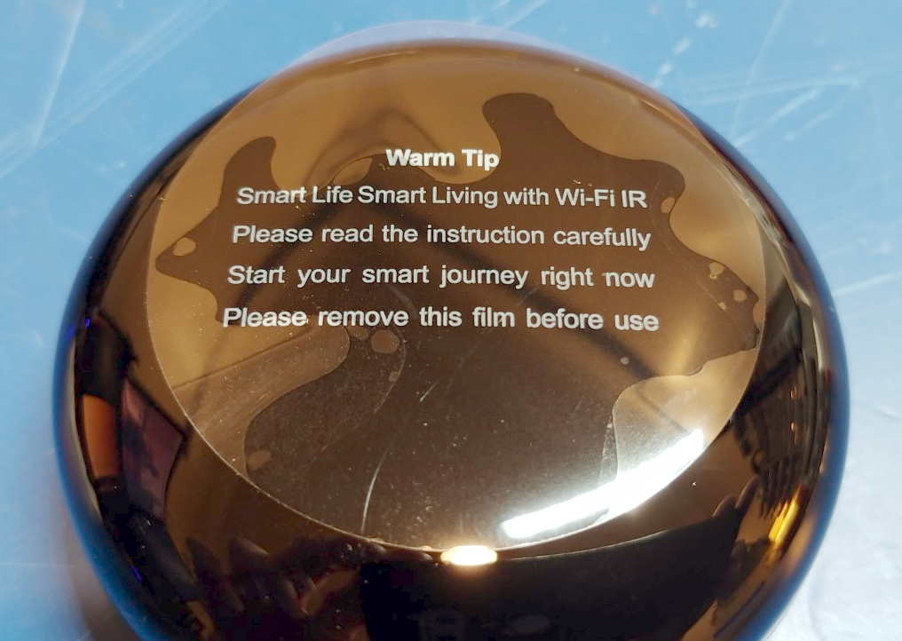
First in typical CircuitSnoop fashion, let’s take a minute to appreciate the great documentation included…
One of the item’s you’ll need for this (and a good thing to have in your toolbox), is a USB to Serial breakout. These are usually named USB TTL adapters, and also readily available for under $10.
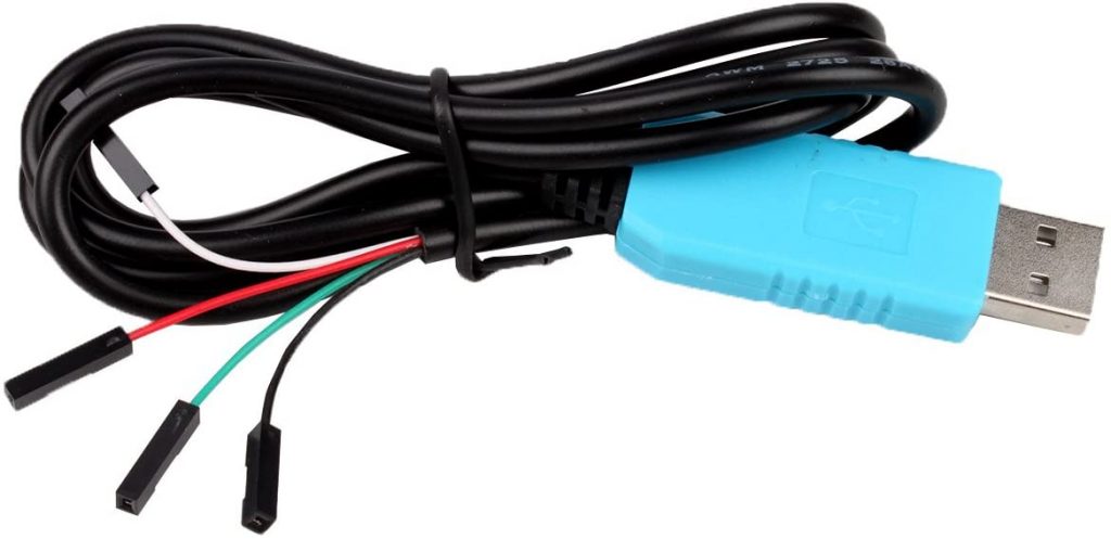
IMPORTANT: Many cheaper USB TTL converters are usually set up for 5V DC level, you’ll need to “convert” it to 3.3V level for any ESP8266 firmware flashing (like this guide). Others have a 5V/3.3V jumper/switch that makes it easy. If you already have one of the preset 5V only ones, it’s usually a simple soldering job after opening up the converter. Find this information online after a simple search. DO NOT PROCEED UNTIL YOU ARE SURE THE VOLTAGE LEVEL IS ON THE USB TTL ADAPTER IS 3.3V DC
Now that you have a 3.3V USB TTL adapter, it’s time to open up the device. This device is usually a plastic “hockey-puck” type form-factor, and you’ll need a thing prying tool to open it up from the sides. I ended up warping the plastic a bit, but it’s possible you just have to really get in there.
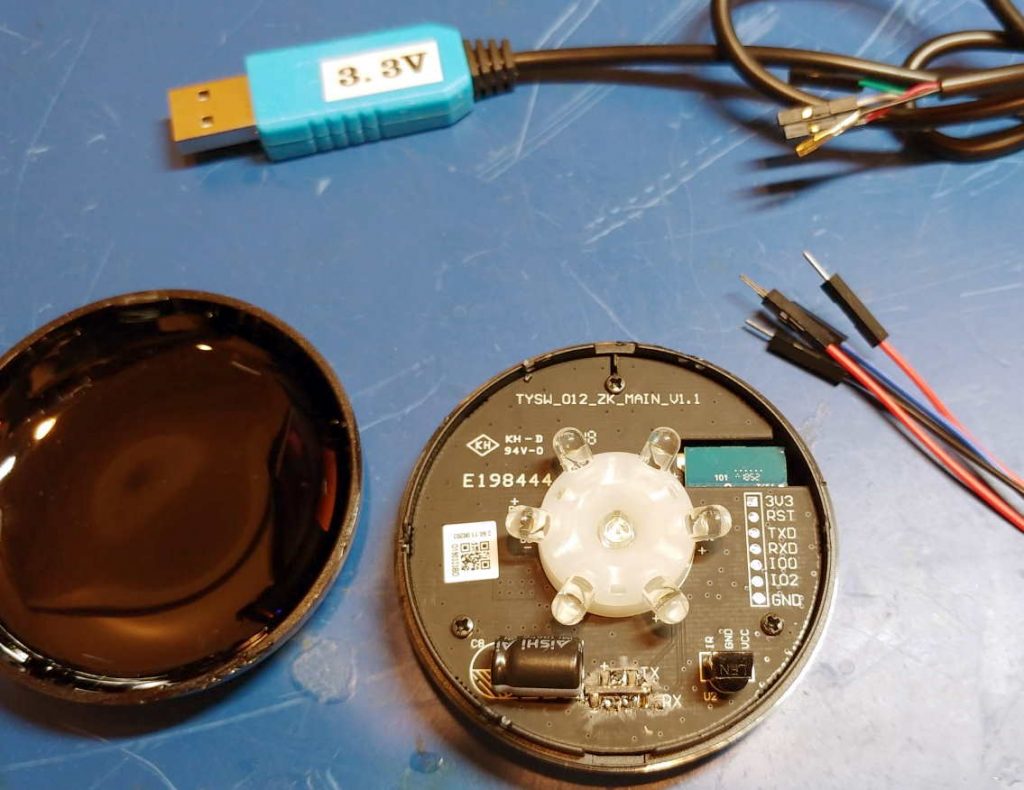
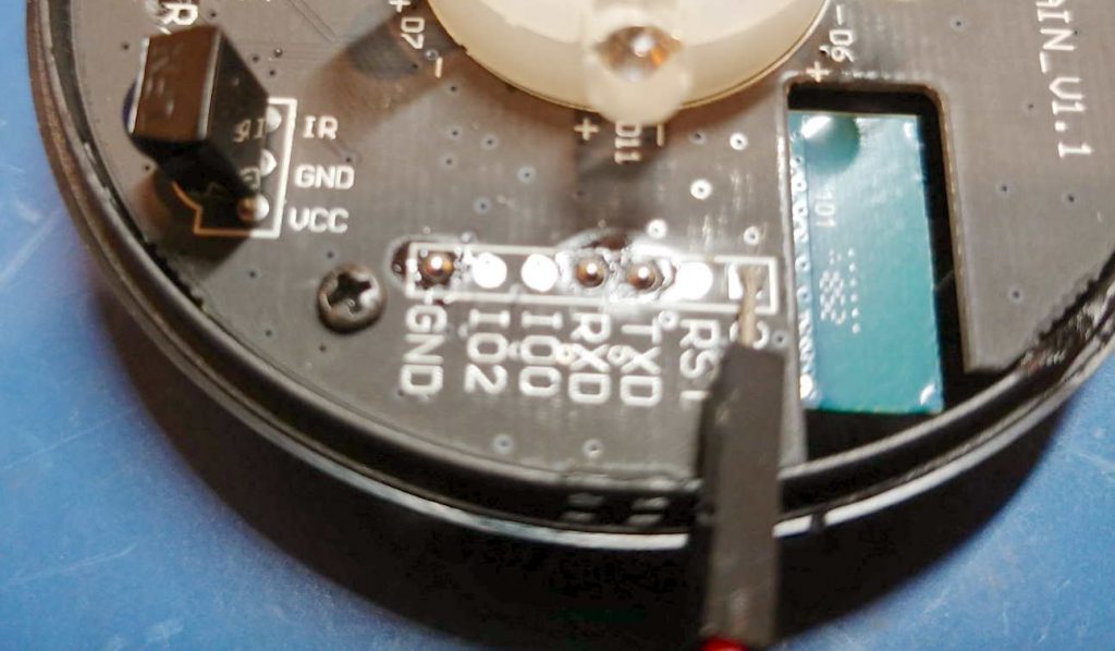
The connections you’ll see that are common to these ESP8266 devices are:
- 3.3V
- GND
- TXD
- RXD
- GPIO0
- GPIO1-n (some have more than others)
So we need to connect the USB-TTL adapter to 3.3V, GND, TXD, and RXD on the device. We need to boot the ESP8266 to “flash” mode to flash Tasmota, there are two options for this:
- Hold the RESET button while powering on
- Connect the GPIO0 to GND
These devices almost always have a “Reset” button exposed somewhere (even without opening it up). You can try this, but for some reason I’ve not had great luck with this method, and instead have to connect GPIO0 to GND.
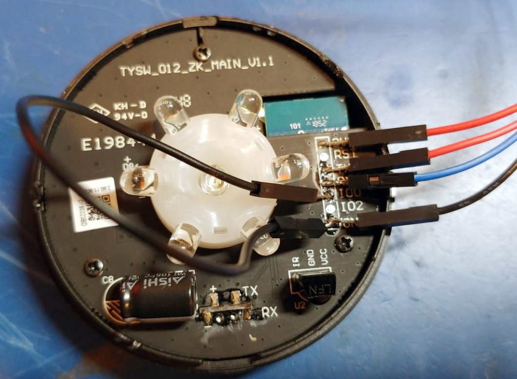
In any case we need to connect the leads of the USB-TTL adapter to pins 3.3V, GND, TXD, and RXD. You can get creative here, but the most stable method is to temporarily solder the leads to the device pins. With this WIFI-IR blaster, the pads are conveniently exposed and labeled. (In some other devices, you’ll have to directly connect to the pins on the ESP8266 chip, which is not always easy)
Flashing Tasmota
Now that we’re all hooked up, it’s time to flash the Tasmota firmware. The Tasmota project page has a detailed guide on this entire process, we’ll summarize it here for this WIFI-IR blaster. For this device, we will use a build of Tasmota that contains a bunch of additional functionality aimed at IR devices, so we will flash tasmota-ir.bin. And, we will use the open-source GUI Tasmotizer to flash the firmware (there are other utilities on the Tasmota guide online). Before flashing let’s confirm that:
- 3.3V, GND, TXD, and RXD are connected up to your 3.3V USB-TTL adapter
- You are set up to boot into “flashing” mode by either: connecting GPIO0 to GND (preferred), or holding the RESET button on power-up
- During the initial flash, you’ll want to make sure the “Erase before flashing” option is checked/set
- Find the COM (serial) port that shows up when you plug in the USB-TTL adapter to your computer
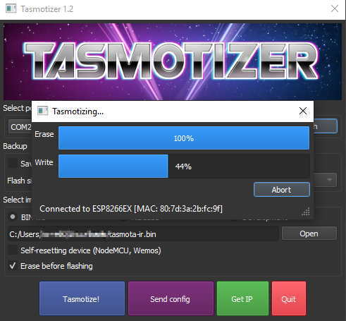
After successful flashing, you’ll get a message to power cycle the device. After you get this message, you can disconnect the USB-TTL adapter, unsolder the connections, and re-assemble the case. Then, we want to connect the regular power plug (micro-USB).
If Tasmota was successfully flashed, the device will initially start in “Wifi-direct” mode. This means is will appear as a Wifi network (SSID), named something like tasmota_FFFFFF-DDDD. You can use your smartphone to connect to this Wifi network, and you’ll be presented with a sign-in page (captive portal), where you can input the Wifi SSID and password of the network you want the device to connect to. Go ahead and input your network information, and click Save.
TIP: Also change the hostname field to something you’d like, so you don’t have to go hunt down the IP address.
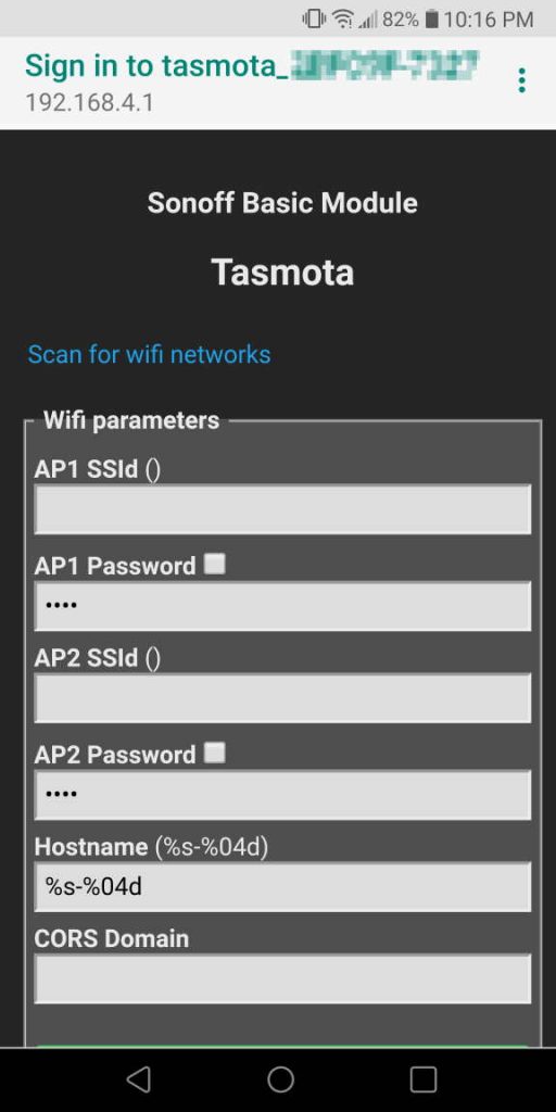
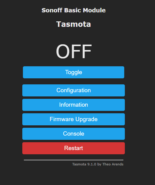
If you’ve set all the information correctly, the Tasmotized WIFI-IR blaster will now connect to the Wifi network you’ve input in the previous step, and you can access it from within a network (by hostname if set earlier, or IP address. Use a network inspector or your network router interface to find it).
Next Steps…
If you’ve gotten this far, awesome! Don’t be discouraged if it took you longer than anticipated, once you’ve done this one time successfully you’ll find flashing other devices to Tasmota much easier.
Now that that Tasmota is loaded, it’s time to see what we can do. Part two of this tutorial will cover:
- Tasmota UI Overview
- Simple IR learning and programming